Thesis
Multi-Robot Collaboration via Contact Perception & Non-Prehensile Object Transportation
At the onset of this project, the fundamental question that I formulated was:
What behaviors and structures will arise from a system coordinating strictly with implicit communication? Additionally, how will tasking this system with transporting an object more massive than one agent of this system adapt to a non-prehensile condition?
With this question, my vision for this project has been a means for robots to be operational alongside humans without barriers or separation. Consequently, enabling robots to directly contact within a complex system may naturally cooperate the individuals for greater system achievements. My desired outcome is creating a system of smaller robots at scale for moving objects rather than singular larger AGVs or AMRs. Lastly, I hope to generally apply this framework to industrial arms and other robotic systems to better generalize to tasks and complex workspaces.
Objectives
- Develop a trajectory planning model suited to dynamic environments with a target position and current position feedback
- Develop a multi-robot system in simulation to identify theoretical behaviors related to varying dynamic properties and number of active agents
- Build a physical concept complemented with testing of current methods for applied force
Background
The theory for this work begins with the spring-mass-damper dynamical system analogy. While this particular work is more abstract from a traditional mechanical system, the foundation of stiffness, damping, and inertia are present throughout this system.
The first dynamical system is in the trajectory planner. The model, known as attractor dynamics, is found in Fajen and Warren’s publications which describe human trajectory planning in the case of obstacles and a target position. Their work describes how an attractor or a repeller within an environment may affect a person’s heading depending on the distance to the target or obstacle. This model is of particular interest because it allows for omnidirectional control. Furthermore, the paths described in their works were dependent on the dynamical parameters which I believed would positively contribute towards system stability. Lastly, the information required for the model is conveniently current position, target position, and obstacle position. The model utilized in this testing is:
\begin{equation}\label{Att Dyn} \ddot{\phi} = -b_{nav} \dot{\phi} -k_p(\phi - \psi_p)(e^{-c_1 d_p} + c_2) + k_r(\phi - \psi_r)(e^{-c_3|\phi - \psi_r|})(e^{-c_4 d_r}), \end{equation}
here $b_{nav}$ is the system damping, $k_p$ is stiffness of the heading towards the target position, and $k_r$ is stiffness of the heading towards the repeller, $psi_p$ is the relative heading to the pushing point, $d_p$ relative distance to the pushing point, $\psi_r$ relative angle between robot and repeller, and $d_r$ as the robot’s distance to the repeller. The remaining terms are user defined tuning constants.
The other dynamical model is an impedance controller. The purpose of this is for the robot to utilize the force feedback and adjust the heading received from the trajectory planner. The adjustment to the heading will depend on the dynamic parameters. However, the goal is to bias the heading towards the “center of contact”. For example if one robot comes into a non-coupled contact with another robot, the heading should be somewhere between the object and the other robot. This will create a group which will be able to maintain their contact while continuing towards the target position. In the case of many robots in contact, it will depend on where the magnitude of force is being observed. The model for this is defined as:
\begin{equation} \label{Altered Imp} m\ddot{x} + b(\dot{x} + \rho) = (f_{d} * F_{scale}) - f, \end{equation}
where $f_{d}$ is the desired force which determines the direction of the applied force, $f$ is the measured force resolved to principal axes, and $F_{scale}$ is a tuning constant to overcome external disturbances and avoid deadlock. The adaptive term $\rho$ reacts to the online force error, such that
\begin{equation} \label{Rho Imp} \rho(t) = \rho(t-T) + \sigma \frac{f_d(t-T) - f(t-T)}{b}, \end{equation}
with $T$ being the sample rate of the system and $\sigma$ directly compensates for accumulating errors caused by environmental stiffness, such that
\begin{equation} \label{Sig Imp} \sigma = \frac{1}{e^{\alpha |\Delta f|} + e^{\beta |\Delta f’|} + U_{limit}}, \end{equation}
where $U_{limit}$ is an upper limit to ensure stability defined as
\begin{equation} \label{U limit Imp} U_{limit} = \frac{m + bT}{bT}, \end{equation}
with $\Delta f$ being the force error and $\Delta f’$ the gradient of the force error.
Testing
The environment setup for the simulation and results collected for this work is illustrated below. The robots are hexagonal in shape and measure force as a resultant decomposed into their local frame. The transported object is cuboid with a mass such that one robot could not move it alone. The center of the object must be moved within a specified goal region. While navigating the workspace, the closest point to the object relative to each robot (at a specified range) is known. On the object surface facing the goal region creates a repeller for the trajectory planner. This limits the interaction which would increase the distance of the object to the goal region. However, on the occluded side of the object, an attractor is applied to the robot’s heading which would encourage the robot to engage the object and push towards the goal region.

Each trial begins with a desired number of robots randomly placed within the environment. However, placement is limited to four specific conditions. In Case 1, all robots are initializes between the object and the goal position. This is theoretically the most difficult case since the robots will have to fully maneuver around the object before pushing may commence. In Case 2, all robots start on the occluded side of the object relative to the goal position, see also Figure \ref{fig:ConvRep} for a definition of occluded space. This is expected to be the most successful case since the robots can immediately prepare to push with minimal maneuvering. In Case 3, the robots are placed lateral to the object. In Case 4, robots are randomly distributed within the workspace.

Further detail on testing parameters can be found in my full thesis on my google scholar link. Additionally, proper citations are there for the specific works referenced in this page.
Outcomes
Upon the completion of my thesis, all three objectives were investigated with key insights and videos discussed below. Particularly, I wanted to highlight the initial condition dependency of this system from the simulation. Below you will see videos from the trials outlined in my thesis. Each one documents a different initial condition case as I describe above. With the videos is a mixed ability to move the object to the desired region, but each demonstrate the wide ranging behavior that arise from this dynamic system proposed.
Simulation
During testing, simulation trials were conducted with the same dynamic parameters and number of active agents. The objects mass and size was consistent and uniform, friction coefficient was left to 1 for simplicity. Each agent received data on its own position, the current position of the object, and the desired final position. No information was given about the other agents within the space or the dynamical properties of the object.
Case 1
Case 2
Case 3
Case 4
While many of these trials did not successfully push the object within the criteria tolerance, many trials were just outside of the specified region and overshot the goal. Additionally, for the given parameters of this testing two cases (case 2 and case 3) had the highest rates of success and more consistent trials compared to the other cases. The number of agents acting within the workspace contributed greatly to the objects path within the trial period. While these robots were randomly placed within the case, an increase or decrease in the number of robots did not prove a predictable relationship for “successful” completion of the task or measurable application parameters. There is a reasonable question of what is an “acceptable” target region for the object. While the region chosen for testing was rather constrained, there were many instances of “successful” trials. Reflecting on this process, more trials than the 10 averaged for each combination for this study may be required for a proper pattern to arise. I also see evidence from some telemetry a lack of condition or refinement in the model. Further study is needed on the stability aspect with a coupled path planning/impedance model as proposed.
Prototype
With the assistance of my senior capstone group (1 Mechanical 2 Computer Engineering students), we plotted out a means to replicate the capabilities of the robots from the simulation. As illustrated in the figures below, the frame was 3D printed out of ABS and the sensors, logic, and power distribution were commodity electronics. Notably, we decided to work with a bi-level logic architecture. A teensy 4.0 handled the sensor sampling while a raspberry pi was high level logic and planning. The force feedback for this system was handled by six load cells with an IMU and encoders for localization.
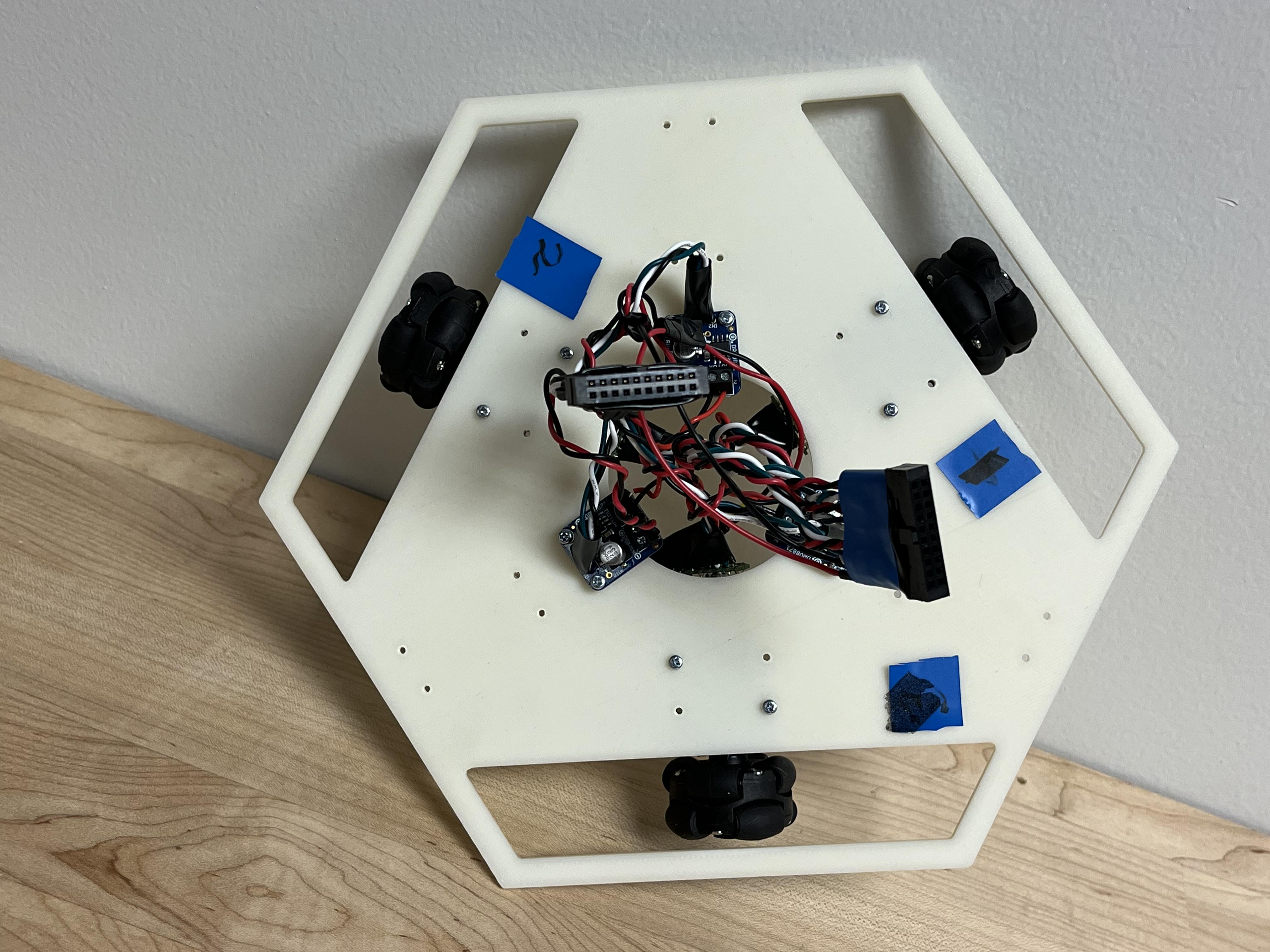
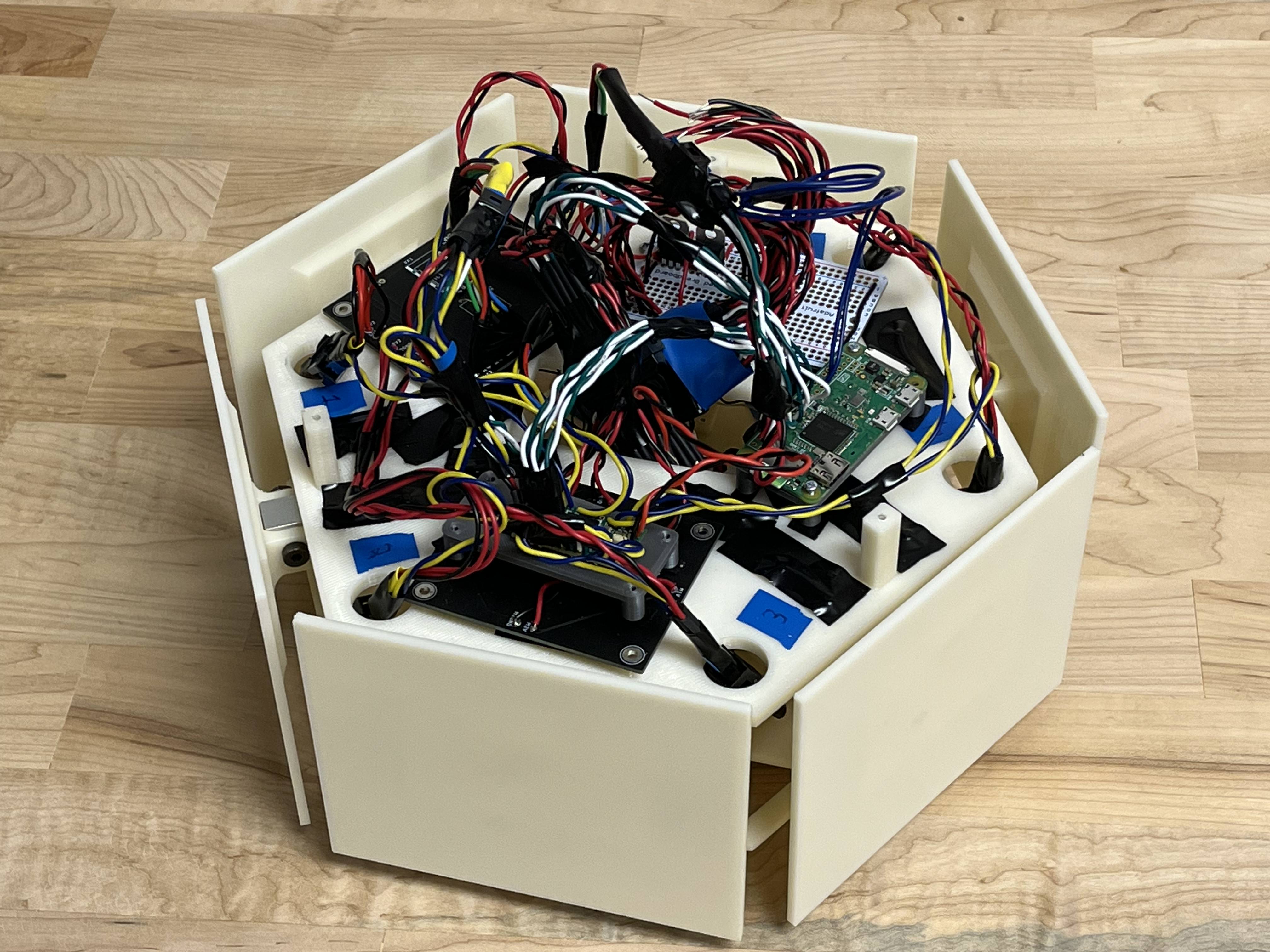
This work was completed within the Embodied and Interactive Systems laboratory at the University of Cincinnati. I also give special thanks to my advisor Dr. Tamara Lorenz for which I am grateful of her guidance and mentorship. My complete thesis is available on my google scholar link on the home page of this portfolio site.
Simulation Challenges
While the scope for this thesis was wide, it holds some exciting challenges. Firstly, coordinating agents with contact as the sole means of communication challenges much of the status quo for mobile robot systems. Many current systems are relying on laser range finder, optical, and/or ultrasonic for localization, object detection and obstacle avoidance. This works perfectly fine in simple, static or mostly static environments. Alternatively if the workspace of a robot with other agents (humans or robots) are in perfect direct communication with each other this perception is non-problematic. However, in practice any unexpected and dynamic agents, obstacles, or features often prove too much information for the aforementioned optical/ultrasonic systems to react quickly. In theory, adding contact feedback provides a last resort for the robot to stop or maneuver instead of stopping or faulting in the case of an unexpected contact. Furthermore, an opportunity for a “language” or queues to form between the robots while completing a task. Ultimately in my work, a simple version of this emerged by maintaining contact with a fellow agent once contact was established. Throughout testing, this could be modulated with the dynamic variables I outlined in my thesis in addition to other variations of the contact behavior. However, this tendency to maintain contact may have been assisted by the common task between the agents.
The next challenge is stability. When connecting the two robots together with minimal communication, each controller instantaneously has a number of new stimuli to overcome. The first is a change in position depending on the impulse of the collision. The feedback of the actuator input and spatial perception may decouple depending on how great the collision is. The next is the stiffness/restitution of the materials of the robot. Many methods have overcome this factor during collision. However, it is still present in the interaction and does impact the physical interaction, especially at scale. The next is a doubling of the inertia of the controller to account (assuming each robot is identical). Lastly is the resistance from the other robots motors. Some energy with this method will always be lost pushing into the other robot while attempting to maintain contact. Ultimately, my testing and controller implementation showed that one additional robot is not an issue. However, when many robots are introduced into the system and encouraged to complete the same task in the same workspace, chaos begins to overtake the system. This presented as many different behaviors. The first was an oscillating motion in the robot which was observed in the heading data as high frequency oscillations. The next was separation from the group near the target object and holding still or “walking” in place for a moment before stabilizing the controller. This was deemed as the “Growing DOF Problem” which was not surmounted in this project. Some of my current thoughts to stabilize this problem revolve around increasing the feedback modalities, further investigating the simulator force calculation, and implementing a reinforcement learning or Convoluted Neural Network/Deep Neural Network methods to improve dynamic stability within the controller.
The last prominent challenge I faced during this thesis project was the lack of support for contact in the traditional ROS/Gazebo simulation pipeline. As mentioned prior, the existing art has many options regarding vision and optical localization and mapping libraries. However, some inspiration may be taken from FEA or other existing stress solvers to better calculate and handle applied and resultant forces in robotic simulations. While some additional time could have been spent on a custom solution, it was a large time investment that was outside the scope of this work. However, after submitting my thesis, I noticed a significant increase in publications proposing various methods of simulated and physical contact methods. The result of this seems to be some development in the simulation space in ROS and other simulators which I hope to contribute to some day.
Physical Prototype Challenges
In translating the simulation space to a real prototype, the first challenge arose. The load cells chosen to measure force were not robust. Notably, once a load cell is overloaded it is no longer usable due to the de-lamination of the epoxy which bonds the strain gauge to the metal substrate. The same is true for shock, even if load is appropriate. While some countermeasures could have been implemented to prevent overloading, shock could not be guaranteed and was a flaw in this design. Furthermore, the load cells are incredibly temperature sensitive and de-laminate outside a small temperature range.
Ultimately, the robot did have some basic movement. However, it did not replicate the simulation behavior and responsiveness to force as expected. The likely culprit for this is the force measurement system and some software bugs preventing data acquisition and flow throughout the controller. If I were to redesign this system, it would be a multichannel force controller where sampling is not directly required. Some of this vision can be seen in my ongoing projects on this site. Another important mechanical design aspect would be some sort of force limitation joint with a spring and fixed range of displacement.